Overview of the EBM usecase
The Salty architecture is composed of managed and managing systems that interact at runtime in order to adapt according to changing context.
They interact thanks to sensors and effectors to respectively retrieve information and command modifications. The link between retrieved information and modifications is made thanks to feedback control loops that can be implemented by MAPE-K loops.
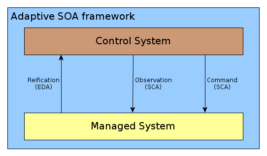
In the context of SOA, some standards and mechanisms seem suitable to face sensors and effectors issues. The following figure represents the chosen ones used in order to build an adaptive SOA framework.

An adaptive SOA framework.
We can see Event Driven Architecture (EDA) to implement sensors and Service Component Architecture (SCA) to observe and command modifications, and thus implement effectors.
From the EBM point of view, this adaptive architecture consists in a deployment of ESB middleware in which BPEL engines are installed in order to execute functional and reconfiguration workflows. Runtime adaptation features expected for Salty are located at functional workflow level. Then our main work in Salty concerns EasyBPEL and more precisely EasyVIPER.
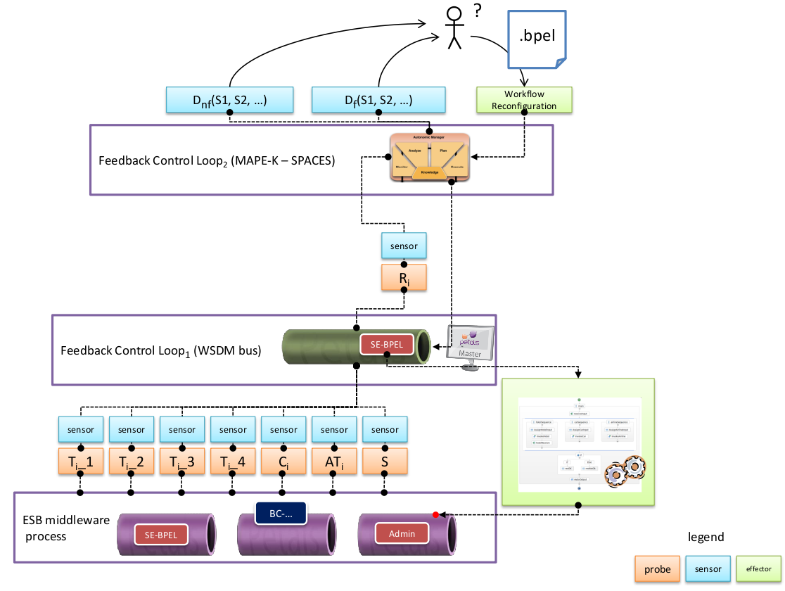
The following figure is a summary of the adaptive architecture implemented in the context of Salty.

The whole EBM usecase architecture.
We can see the managed system is a set of Petals ESB nodes, that embed EasyBPEL engine to execute a business workflow. In the context of Salty, this workflow is a crisis management one, able to solve chemical, biological, radiological, and nuclear crisis. A set of sensors are placed at this level, onto which the first feedback control loop (FCL) can subscribe to.
The represented probes sent by sensors are, on one hand, the 4 main timestamps during a service invocation within the bus:
- T i _1 is set when the request of the client is entering the bus,
- T i _2 is set when the request of the client reaches the invoked service,
- T i _3 is set when the response of the service is entering the bus,
- T i _4 is set when the response of the service goes outside the bus.
On the other hand, some functional probes are retrieved in order to control precisely the crisis workflow:
- C i is the heart rate of the i th fireman service.
- AT i is the blood pressure of the i th fireman service.
- S is the status of the crisis.
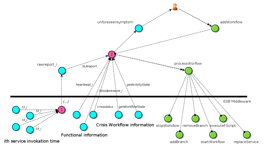
This first FCL is actually a particular node of Petals ESB (or several ones) enhanced by a WSDM profile. This particular feature allows it to receive data in order to detect agreements violation (defined in a first time). A lookup table is built at this level between SLA violations and corresponding reconfiguration actions. These reconfiguration actions are exposed by a particular service of the BPEL engine and are described by the following figure.

EBM usecase with the Salty framework view.
Command actions are (start)stopWorkflow, replaceService, removeBranch, executeFScript (blue ones are work in progress).
In the case of a more complex adaptation action (that would consists in a combination of these unitary actions), a BPEL workflow appears well suited to orchestrate the reconfiguration. These reconfiguration BPELs are executed by a dedicated BPEL engine located on the FCL node of Petals ESB.
This look-up table can be filled at deployment or, in a more interesting way, it can be fed along the workflow execution, thanks to the second FCL. Indeed, in case of a unknown SLA violation, for which no reconfiguration action is foreseen, an indirection is made on the second FCL. In this higher level adaptation process, an expert can design (or select or configure) a particular BPEL in order to add a tuple in the first FCL table.
Finally, if a violation is detected (a partner down for instance), a reconfiguration action or BPEL is selected, stored and executed in order to adapt the running workflow (replace a missing partner for instance).